 Myers Construction Myers Construction
|
Common Engineering Problems in Frame ConstructionFrom undersize nails to overloaded trusses, here's a look at what builders get wrong when they wing it without an engineer by David UtterbackOver the past 22 years as a builder, building inspector and lumber-industry representative, I've inspected a great deal of framing in all parts of the country. Terms and techniques vary from region to region, but mistakes don't. The same problems tend to show up over and over. In this article, I'll examine some of these problems from an engineering standpoint and look at what can be done to avoid them. All these situations are addressed in similar ways by each of the three major building codes. Before going further, I must emphasize that difficult framing problems often require complex engineered solutions. When the going gets tough, your best bet is to enlist the services of a good engineer. It's a lot cheaper than defending yourself in a lawsuit. Joist-hanger nails are not meant for installing joist hangers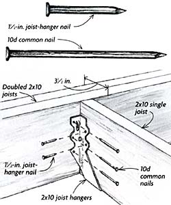 Joist hangers are marvelous devices for supporting joists or beams that cannot rest directly atop vertical framing members. To get the most structural capacity from a joist hanger, you must use the correct hanger for the joist and place the right nail in every nail hole. Many builders mistakenly assume that the right nails for every situation are the 1-1/2-in. long "joist-hanger nails" sold by the manufacturer. In truth, these nails are intended for anchoring the sides of the hanger to a single joist without piercing the other side. Joist-hanger nails are too short for some applications The 1-1/2 in. long joist-hanger nails are primarily intended to attach the hanger to the sides of a single joist. For maximum strength, full-length 10d common nails (or 16d sinkers) should be used to fasten the joist hanger to the beam. Joist-hanger nails have the same diameter, and therefore the same shear capacity, as 10d common nails, but their shorter length gives them less withdrawal resistance. For maximum strength, nothing smaller than 10d common nails (or 16d sinkers, which have the same diameter) should be used to attach a single joist hanger to a beam. Sixteen-d commons should be used to attach a double joist hanger to a beam. This fact does not mean that you can never use the short nails to support a joist hanger. But if you do, you must reduce the load. If joist-hanger nails are used instead of 10d commons to support a single hanger, you can use only 77% of the load value of that hanger. If they are used instead of 16d commons to support a double hanger, that load capacity drops to 64%. It's always wise to check with the hanger manufacturer if you are not sure what size nails to use. Some hangers have the required nail size stamped directly on the hanger. Besides nails, you also need to understand the differences between hangers. Some hangers have little dog ears on the side of the hanger sticking out at 45° angles (I've seen framers bend the ears over to get them out of the way). These hangers require what is called double-shear nailing: Common nails are driven through these holes at an angle into the joist and on into the supporting beam or header, distributing the load through two points on each joist nail for greater strength. If you use this type of hanger, make sure it is nailed correctly.
Load-bearing cantilevers need careful engineeringMany builders lay out cantilevers according to a simple rule of thumb: "One out, two in." This rule means that for whatever length the joists extend past their bearing point, they should run back in at least twice as far. While technically correct, the rule applies to non-load-bearing applications only, and even then has its limits. In nonbearing applications, a joist may not cantilever more than four times its depth. Therefore, a 2x10 joist should cantilever no more than 37 in. (4 x 9-1/4 in.), regardless of its length. Non-load-bearing cantilevers can include sun decks and even bay windows (the cantilever supports only the weight of the window; any loads above are carried on a header set into the main wall). On the other hand, a zero-clearance fireplace with a two-story wood-frame chase would impose a significant bearing load on a cantilever. Some simple load-bearing cantilevers can be built without paying an engineer. Because loads transfer through solid-sawn joists at 45° angles, codes allow load-bearing cantilevers that extend the same distance as the joists are wide. In other words, you could set a bearing wall on the end of 2x10 floor joists that are cantilevered 9-1/4 in. without risking a correction notice. Cantilevered joists that run perpendicular to the main floor joists may have another problem: If the connection between the two is not constructed properly, a teeter-totter effect could force the inside edges of the cantilevered joists upward, creating a hump in the floor. To prevent this unpleasantness, the cantilevered joists should butt into a main joist that has been doubled to serve as a header. The connection between the cantilevered joists and the header should be securely constructed to prevent independent movement. As an added measure, subflooring should overlap the joint where the cantilevers and the main joist meet. Bearing walls should line up with their supports To transmit loads smoothly from roof to foundation, bearing walls must be stacked closely above one another. Where I-joists are involved, each bearing wall must sit directly over the top of its support because the web of an I-joist has little cross-sectional strength. Solid blocking or squash blocks also need to be installed according to the manufacturer's instructions to carry the load around the web and prevent the web from buckling. Supporting bearing wallsWhen solid-sawn floor joists are used, bearing walls may be offset a distance equal to the depth of the joist. To keep the joists from rolling over, full-depth solid blocking is required between the joists where they rest on the bearing walls. Solid-sawn floor joists have more cross-sectional strength than I-joists, which allows you a little bit of leeway if you need to offset a bearing wall from its support. You can basically treat this situation the same as you would a load-bearing cantilever, meaning you could offset the bearing walls the same distance as the depth of the floor joist. If you had a 4-1/2-in. wide flange supporting 2x10 floor joists, you could set a bearing wall 9-1/4 in. to each side of the beam's edge and still meet code, giving you almost 2 ft. to play with. To prevent rotation of the joists, the codes also require full-depth solid blocking over beams or over bearing walls that support floor joists. As lateral loads, such as wind, are placed on the building, they're transferred into the floor diaphragm through the joists on their way to the foundation. By themselves, the nails that attach the plywood subfloor to the joists do not have the strength to resist these forces; if the floor joists are not blocked, they could actually roll over and end up lying flat. Because the tiny return walls on each end of the three-car garage could offer little resistance, lateral loads from an earthquake literally twisted this house off its foundation. The structural integrity of the rest of the house was largely unaffected. Garage walls and cripple walls need extra bracingMost regions of the country aren't threatened by earthquakes, but nearly every place is exposed to high winds. It is extremely important that walls be properly braced to resist these lateral loads, or the results could be catastrophic. Builders can generally rely on structural sheathing to brace walls, but that's not always enough. Among the weakest points in a house frame are the narrow return walls on the sides of the garage door (see Wider is better). Tall narrow walls are inherently difficult to brace properly against high lateral loads; this fact is why the Uniform Building Code (UBC) now requires a minimum 2-ft. 8-in. width for garage return walls. If you absolutely must squeeze in space for three cars, you can build a shear wall on site -- by following a precise schedule for framing, nailing and bolting -- that will allow you to reduce this width to 24 in. or possibly even 16 in. Cripple walls (short kneewalls that run between the mudsills and the first-floor joists) are another weak link in the structural chain. Besides transferring vertical loads through to the foundation, these walls must also resist lateral loads. Cripple walls are effectively shear walls, and as such, they must be braced with structural panels and nailed at 6 in. o. c. to provide the shear resistance necessary to support the structure above. Another bracing point often overlooked is the connection between first-story and second-story walls. Most of the time, builders brace these walls independently of each other. Because lateral loads such as high wind can impose torque (turning or twisting energy) on a building, the upper story will move more than the lower story if the two aren't tied together. Fortunately, these walls can be tied together easily. One solution is to overlap the sheathing panels between floors (blocking the panel edges may be necessary in areas that are subject to high lateral loads). If sheathing is already in place, another solution is to tie the lower studs to the upper ones using metal straps specifically manufactured for that purpose. Think twice before cutting beams It's easy to pull out a saw and cut off the top corner of a beam that must be kept beneath a roofline. But if too much cross section is removed, shear forces can cause the beam to split and eventually to fail. For solid-sawn beams, you should leave at least half the width of the beam above the supporting wall and confine the length of the tapered cut to no more than three times the original width of the beam. If you don't have room to leave this much cross section, your best bet is to lower the beam (set it in a pocket) or have a tapered beam engineered. Where to cut or drill beamsPlumbers, electricians and HVAC installers are as guilty as carpenters when it comes to carving -- and weakening -- beams. Here's a brief rundown on what the codes allow. Solid-sawn beams may be notched one-quarter their depth at the ends and one-sixth their depth in the outer thirds of the span. Holes may be drilled in a beam from face to face, but never from edge to edge. The diameter of the hole may be as big as one-third the depth of the beam, but it must be at least 2 in. from the top or bottom edge. Rafter ties must be near the plates to be effective Many builders confuse collar ties with rafter ties. Both are horizontal framing members that connect rafters, but that's where the similarities end. Collar ties (which are required by the Southern Building Code and no other) function to resist the pressures of wind uplift on a roof by holding the rafters together where they meet the ridge. As high up as they are, collar ties have no leverage to prevent the rafters and walls from spreading outward. That job is best done by the ceiling joists. The wrong and the rights of rafter tiesTo prevent roof loads from spreading the walls outward, rafter ties (or ceiling joists) must be in the lower third of the roof pitch. Collar ties are too high to keep walls from spreading and instead serve to resist uplift by holding the rafter together at the ridge. If there are no ceiling joists or if the joists run perpendicular to the rafters, then the code requires rafter ties. Similar to a ceiling joist, a rafter tie is typically a 2x4 that runs parallel to the rafters, from outside wall to outside wall, and ties the rafters together as close to the top plate as possible. Rafter ties need to be installed every 4 ft. down the length of the roof. Rafter ties do not have to be at ceiling height to be effective, but they must not be placed any higher than the lower third of the roof pitch. In other words: Measure vertically from the outside wall's top plate to the bottom of the ridge, and place the rafter ties within the lower third of that measurement. Once they get above that point, they lose their most effective leverage. I've seen builders compound their mistakes when they try to use rafter ties as ceiling joists in semivaulted ceilings. For maximum headroom or aesthetic balance, they place the rafter ties halfway up the roof pitch, near the center of the rafter span where they're too high to be an effective tie. Applying the insulation and the drywall greatly increases the load on the rafters at their most critical point: midspan (what engineers call the maximum bending moment). This added load can cause the rafters to sag, pulling the ridge down and also pushing the exterior walls outward. To avoid this problem, you'd need to engineer the rafters to carry the point load created by the additional weight being placed on them. You'd also need to design a ridge beam capable of supporting the roof load, just as you would if it were a cathedral ceiling, which essentially it is. Trusses require precise permanent bracingAny builder who's ever heard the words domino effect knows it's important to brace trusses as they are being erected. But not everybody understands what permanent bracing involves. To ensure a stable, long-lasting roof, most truss systems require three types of permanent bracing: continuous lateral bracing of the top and the bottom chords; and diagonal bracing at the end of the building, and in between, if necessary. The bracing for the top chord is typically satisfied when the roof sheathing is applied. The bottom-chord bracing is normally accomplished by placing a row of 2x4s on top of the bottom chord and then running them alongside a panel point (the point where the webs and the bottom chord meet) for the full length of the building. In a wide building, these bottom-chord braces should be roughly 10 ft. o. c. The diagonal bracing -- actually a form of X-bracing -- is the one builders often get wrong or omit altogether. Diagonal bracing should be placed at each end of the building and every 25 ft. along the length of a long building. To prevent the domino effect, the first leg of the X is formed by a 16-ft. 2x4 running down at a 45° angle (or less) from the ridgeline of the gable-end truss to the bottom chord of the farthest reachable inner truss. To take the hinge effect out of the connection between the gable wall and the gable truss, the other leg of the X runs from the top plate of the gable-end wall upward to the top chord of the same inner truss to which the first leg is attached. It's also important to make sure the braces are run alongside the webs of the intervening trusses and securely nailed to each truss. In certain situations, it may also be necessary to brace long web members that are in compression to prevent them from buckling under load. If any web bracing is required, the proper procedure for it will be noted in the technical design sheet that comes from the manufacturer. Placing too big a pile of sheathing on an unbraced truss roof can lead to disaster. Amazingly in this case, the falling dominos were halted when a quick-thinking carpenter was able to brace the remaining upright trusses before the collapse reached the part of the roof where he was working.
Loads must be placed carefully atop trusses After the trusses are placed and braced -- and before the crane operator is allowed to leave -- many builders lift pallet loads of sheathing panels onto the trusses for easy access by the framers. Although this practice may be convenient, it can greatly overload the trusses if not done carefully. On steep roofs, the crew typically erects a temporary platform to hold sheathing. This platform usually consists of two legs resting on the trusses, plus some framework to support the sheathing horizontally. This arrangement puts most of the load on two trusses. The higher on the roof these loads are placed, the greater the stress factor. Severe bowing or total collapse of the trusses can result if the stress is too great. The proper way to load pallets of sheathing on the roof is to place the load as low as possible on the trusses. The type of platform I just described is fine, but set the legs down onto the top plate of the exterior wall. This way, the wall -- not the trusses -- shoulders most of the burden. 
 On this steep roof, sheathing has been stacked too high and is seriously overloading several trusses. A strong gust of wind is all it may take to bring down this house of cards. Even though it's more than a full pallet, this sheathing is stacked low on the roof, and the weight is bearing on the walls. Former builder David Utterback is a certified building inspector who conducts seminars on building codes and wood-frame construction. Photos courtesy of the Western Wood Products Association |
|